Connection Diagram Sub Cooling

Hvac Subcooling Charging Method Explained 3 relays: main fan relay 1, main fan relay 2, and sub fan relay. subaru radiator fan wiring diagram with engine running but no cooling needed. power to the control coil of main fan relay 1 is provided by fuse 26. the control coil on main fan relay 2 also gets power from fuse 26. no cooling is needed, so no power is switched to the radiator fan. Here's a chart that shows the operation of the fans depending on vehicle speed, engine temperature and a c operation: obviously, the fact that both fans were running with the a c on indicates that the sub fan motor is "alive". main fan relay 1 removed and mb 7 and mb 8 shorted. a c off: main on, sub off.

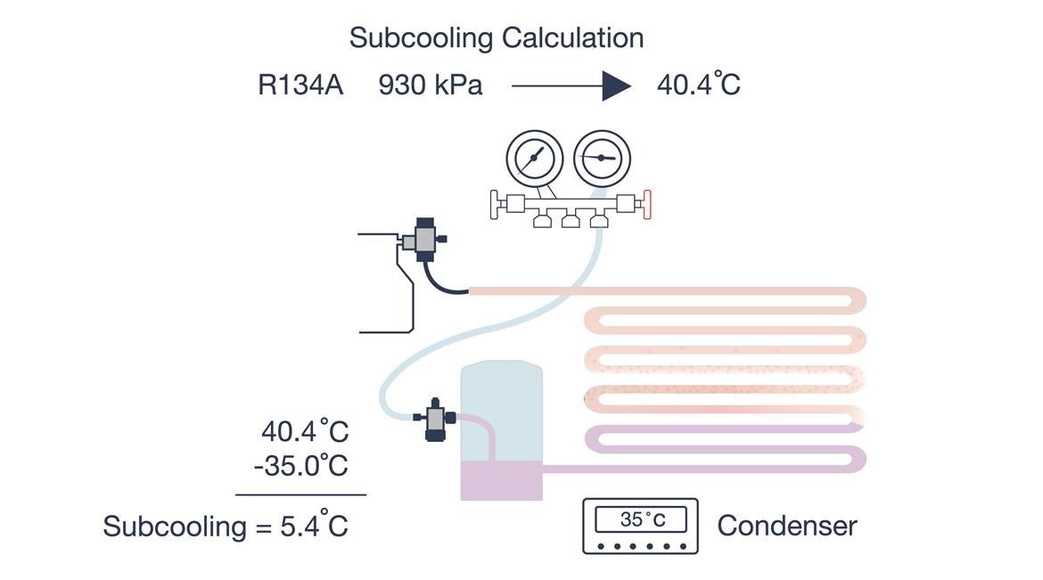
How To Measure Sub Cooling Technical Passport Marine Refrigeration Courses Nspectionoperating condition:radiator fan operates depending on the radiator fan speed related to engine coolant temperature or the ra diator fan speed related to a c compressor load, whichever. is higher as a load condition. radiator fan speed relate. kgf cm2, 725 psi)diagnosis:radiator main and sub fans do not rot. 1) connect the test mode connector. 2) turn the ignition switch to on. 3) using subaru select monitor, check the compulsory operation of radiator fan. n o te: with subaru select monitor when checking the compulsory operation of radiator fan, the radiator main and sub fan repeat the rotation in order of following: low speed rotation o high speed. With our newfound knowledge of how to read the p h diagram, we can easily see that the compressor increases the pressure of the refrigerant, since the line is moving up. the compressor also superheats the refrigerant a bit, since the line moves out to the right of the saturation dome. point 2: here’s our condenser line. The clamp on thermometer reads 77°f. here is how we use the subcooling formula to manually calculate the subcooling in this system: subcooling (r 22) = 89°f – 77°f = 12°f. we see that the calculated subcooling for r 22 refrigerant in this system is 12°f. this is the manual calculation.

Sub Cooler Gas Stream Coolers Sub Cooling Towers Erg With our newfound knowledge of how to read the p h diagram, we can easily see that the compressor increases the pressure of the refrigerant, since the line is moving up. the compressor also superheats the refrigerant a bit, since the line moves out to the right of the saturation dome. point 2: here’s our condenser line. The clamp on thermometer reads 77°f. here is how we use the subcooling formula to manually calculate the subcooling in this system: subcooling (r 22) = 89°f – 77°f = 12°f. we see that the calculated subcooling for r 22 refrigerant in this system is 12°f. this is the manual calculation. With dual cooling fans, there are two methods for wiring up the relay kit. this is based on the draw from the fans, if the fans are larger and draw more than 15 amps each, it's recommended to install a second relay kit as shown below. for smaller fans, both fans can be connected to a single relay as shown above, and the proper fuse should be. Find the temp control switch. it is located on the bottom of the lower intake manifold right in the center towards the engine. it has a single wire going onto a threaded post. take the connector off and ground it with the ignition on. your fan should start. if not, then you need to check the continuity of the wiring.

Comments are closed.