Draw A Flow Chart The Show The Water Distribution Of Water Treatment

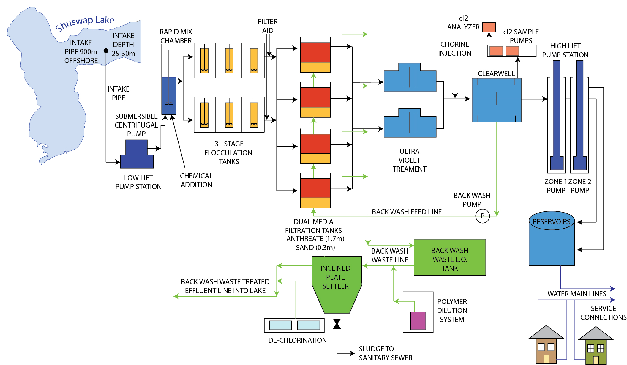
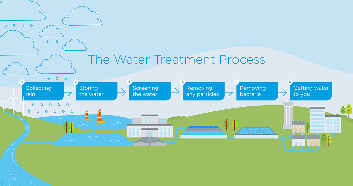
Water Treatment Flow Chart A potable water treatment process flow diagram outlines the steps involved in treating water for drinking purposes. it provides a visual representation of the various treatment processes, such as coagulation, flocculation, sedimentation, filtration, and disinfection, which are essential for removing impurities and ensuring the water is safe for. Drinking water treatment. sedimentation. the heavy particles (floc) settle to the bottom and the clear water moves to filtration. storage. water is placed in a closed tank or reservoir for disinfection to take place. the water then flows through pipes to homes and businesses in the community. flocculation. &. clarification.

Diagram Process Flow Diagram Water Treatment Mydiagram Online 3. coagulation and flocculation. after aeration, coagulation occurs to remove the fine particles (less than 1 µm in size) suspended in the water. in this process, a chemical called a coagulant (with a positive electrical charge) is added to the water, which neutralizes the fine particles' negative electrical charge. A well designed water treatment plant follows a specific process flow diagram to effectively remove impurities and contaminants from raw water sources. in this comprehensive guide, we will break down the different stages of the water treatment plant process flow diagram to help you understand how it works. 1. raw water intake. The treatment component of a water flow diagram includes any processes or facilities involved in purifying or conditioning the water, such as filtration, disinfection, or chemical treatment. 4. distribution: after treatment, the water is distributed to various points of use. this component includes the network of pipes, valves, and fittings. The disinfection process is an important step in water treatment plants to ensure the elimination of harmful microorganisms and bacteria. it is essential to protect public health by preventing the spread of waterborne diseases. chlorination: chlorine is commonly used as a disinfectant in water treatment plants. it is added to the water in.

Flow Diagram Of Water Distribution System Download Scientific Diagram The treatment component of a water flow diagram includes any processes or facilities involved in purifying or conditioning the water, such as filtration, disinfection, or chemical treatment. 4. distribution: after treatment, the water is distributed to various points of use. this component includes the network of pipes, valves, and fittings. The disinfection process is an important step in water treatment plants to ensure the elimination of harmful microorganisms and bacteria. it is essential to protect public health by preventing the spread of waterborne diseases. chlorination: chlorine is commonly used as a disinfectant in water treatment plants. it is added to the water in. This is the first stage of water treatment plant known as pre treatment. the pre treatment process involves physical treatment methods that help remove large solid particles, such as leaves, branches, twigs, sand, and gravel. one of the most commonly used pre treatment methods is screening. the process involves passing the raw water through a. They are typically made of copper or plastic and connect to a distribution main and run to the customer’s parcel, connecting to a water meter. the picture below refers to the “distribution main” as a water main and the “service lateral” as a service line. figure 1.6.2 1.6. 2: – service laterals.

Water Treatment Process Diagram This is the first stage of water treatment plant known as pre treatment. the pre treatment process involves physical treatment methods that help remove large solid particles, such as leaves, branches, twigs, sand, and gravel. one of the most commonly used pre treatment methods is screening. the process involves passing the raw water through a. They are typically made of copper or plastic and connect to a distribution main and run to the customer’s parcel, connecting to a water meter. the picture below refers to the “distribution main” as a water main and the “service lateral” as a service line. figure 1.6.2 1.6. 2: – service laterals.

The Water Treatment Process Santa Clara Valley Water

Comments are closed.