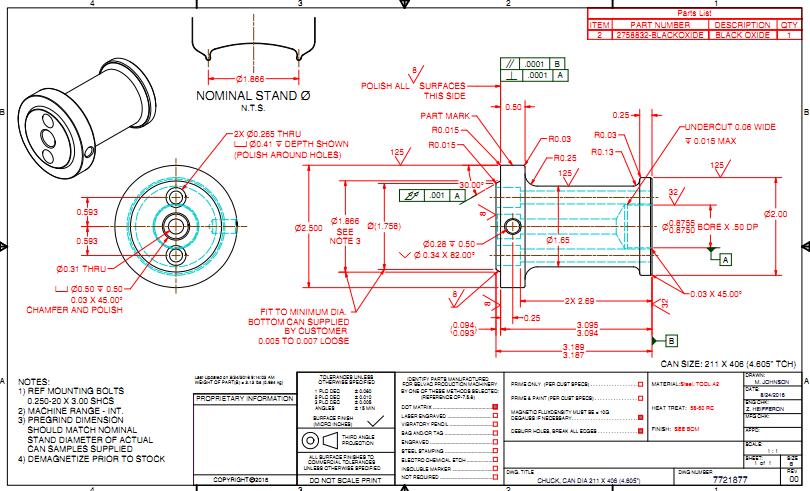
How To Read Machining Drawing Precision Machining Shop

How To Read Machining Drawing Precision Machining Shop The purpose of reading machining drawing is to clarify the structural shape,size and technical requirements of the machined parts.so as to guide production and solve related technical problems, which requires engineers and technicians to have the ability to read machining drawings proficiently. 1. basic requirements for reading part drawings. Let’s begin. first we need to understand what the numbers we are working with represent. whether they are a reading on a micrometer, a spec on a blueprint or a stack of gage blocks, the goal is the same. we need to know how to read them and work with them. below is a graphic that shows the name (including machine shop lingo) for different values.

Machining Drawing At Paintingvalley Explore Collection Of Machining Drawing Units of measurement. the units of the print are very important because there is a huge difference between 25.4mm and 25.4 inches. the measurement units will often be called out in the title block or tolerance block but occasionally will be in another section of the blueprint such as in the notes. angular units are important also but there is. Blueprint reading guide. whether you’re new to machining, want to figure out that never before seen drawing symbol, or simply need a refresher, this is your home to learn more about engineering drawings and blueprints for machining. Introduction to machining another example of a three view drawing: figure 3.1.6 shows a 3 view representation of the support bracket from figure 3.1.5. note that on standard drawings the specific views will not be labelled. more than 3 orthographic views are rarely required to fully describe (and dimension) a part. Cnc machining drawings are primary to any machining process. it is essential to understand the structure of the cnc machining drawings. here is a stepwise guide: step 1: define the most critical views and position the relevant orthographic at the drawing’s center with enough space between them for the dimension details.

How To Prepare A Technical Drawing For Cnc Machining 3d Hubs Introduction to machining another example of a three view drawing: figure 3.1.6 shows a 3 view representation of the support bracket from figure 3.1.5. note that on standard drawings the specific views will not be labelled. more than 3 orthographic views are rarely required to fully describe (and dimension) a part. Cnc machining drawings are primary to any machining process. it is essential to understand the structure of the cnc machining drawings. here is a stepwise guide: step 1: define the most critical views and position the relevant orthographic at the drawing’s center with enough space between them for the dimension details. Step 5: dimensioning: use proper dimensions to specify the size and location of the features that can be seen clearly on the part. ensure the use of geometric dimensioning and tolerancing (gd&t) when such geometry is necessary. step 6: review and validation: revise and check the technical drawing for compliance. Mastering the art and science of reading 2d drawings is integral to achieving precision and accuracy in cnc machining. by understanding the nuances of drawing elements, deciphering the complexities, and rectifying any discrepancies, you can ensure that the final part aligns with the design intent flawlessly.

Comments are closed.