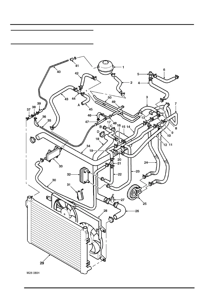
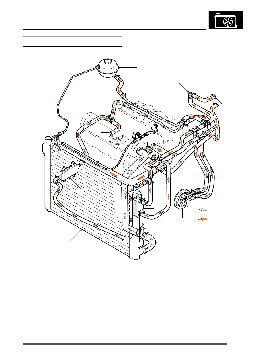
Land Rover Freelander 1 8 Cooling System Diagram

Land Rover Workshop Service And Repair Manuals Freelander System Description And Operation Do you need to service the cooling system the land rover freelander 2006 to 2014 but don't know where to start? this video tutorial shows you step by step ho. Member. hi, has anyone got a diagram of the coolant system for a 2005 facelift 1.8 k series. i've replaced some of the hoses and my vehicle seems to have a long hose from the low water level sensor, across the back of the engine and around to the front and attach to a fitment directly underneath the thermostat (see attached image).

Land Rover Workshop Service And Repair Manuals Freelander System Description And Operation Freelander 2001 to 2004 my onwards workshop manual system description and operation publication part no. lrl0351 nas 5th edition published by land rover. 26 cooling system new range rover 8 description and operation cooling system coolant flow from 99my 1. heater matrix 2. throttle housing 3. throttle housing inlet hose 4. throttle housing return pipe 5. radiator top hose 6. coolant pump 7. manifold outlet pipe 8. viscous fan 9. radiator 10. engine oil cooler 11. gearbox oil cooler 12. 13.8k. posted november 29, 2007. the 1.8 engine is the k series rover engine. the cooling system has to be bled if it has been drained. i start the engine and slowly fill it with the engine ticking over. the bleed valve is on the passenger side under the coil pack. there's a thin pipe coming from the inlet manifold to the header tank and a. Cooling system k series kv6. 26 3 8. description and operation. operation. general when the engine is running, the coolant pump draws coolant through the pipe connected to the thermostat housing and pumps it through the outlet at the right front corner of the cylinder block and through the cooling jackets in the cylinder block, cylinder heads and inlet manifolds.

Comments are closed.