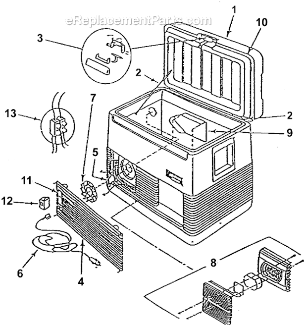
Marlboro Red Cooler Wiring Diagram

Coleman 5232b803 32 Quart Red Marlboro Thermoelectric Cooler Oem Replacement Parts From Coleman 32 quart red marlboro thermoelectric cooler 5232b803 ereplacementparts com. thermoelectric cooler controller design made simpler features feb 2013 photonics spectra. garosa semiconductor cooling peltier refrigeration 12v 4 chip tec1 12706 diy thermoelectric cooler air device canada. 12v 50w peltier refrigerator electronics projects circuits. 6) run wiring, in accordance with local and national electrical codes, to suit the installation. 7) connect the wires in accordance with the wiring diagram below (wiring diagram also located inside lid of appliance control box). warning: use the jumper wire between link and nlink only when fan and pump voltages are the same. model 110423 1.

Cooler Complete Wiring Cooler Connection With Regulator Switch Youtube The new thermostat, mastercool 110423 2. backlight comes on when breaker is closed, but nothing on screen is shown and buttons do nothing. wires behind thermostat. note that the new thermostat uses red, black, and another wire, skipping blue (end wrapped in electrical tape) also visible is two white wires connected with a wire nut, coming from. Proper installation and wiring are essential for the optimal functioning of the evaporative cooler. the wiring diagram of an evaporative cooler includes various components that work together to ensure efficient cooling. these components include a motor, pump, thermostat, and junction box. the motor powers the fan, while the pump circulates. Gather the necessary tools and materials. before starting the wiring process, make sure you have all the required tools and materials. this includes a screwdriver, wire strippers, electrical tape, wire nuts, and the evap cooler wiring diagram provided by the manufacturer. 2. turn off the power. Typically the color coded connections should be made as explained in the following steps. connect the green wire to the ground in the 120 volt circuit. connect the red wire to the low fan speed in the control circuit. connect the black wire to high fan speed in the 120 volt circuit. connect the white wire to neutral in the 120 volt circuit.
Cooler Motor Wiring Diagram Gather the necessary tools and materials. before starting the wiring process, make sure you have all the required tools and materials. this includes a screwdriver, wire strippers, electrical tape, wire nuts, and the evap cooler wiring diagram provided by the manufacturer. 2. turn off the power. Typically the color coded connections should be made as explained in the following steps. connect the green wire to the ground in the 120 volt circuit. connect the red wire to the low fan speed in the control circuit. connect the black wire to high fan speed in the 120 volt circuit. connect the white wire to neutral in the 120 volt circuit. This will help prevent any loose wires or electrical hazards. test the motor: after wiring the motor, it’s important to test it before sealing up the wiring connections. turn on the power to the swamp cooler and switch on the motor. ensure that it operates smoothly and at the desired speed. Connects to the power cord’s green wire (ground) red. connects to the switch’s red wire. blue. connects to the motor’s blue wire. yellow. connects to the motor’s yellow wire. important: before attempting to wire a swamp cooler plug, it is crucial to ensure that the power is switched off and that the wires are properly insulated.

Comments are closed.