Nema 14 20p 2 Speed Cooler Motor Wiring Diagram

Nema 14 20p Wiring Diagram Wiring Draw And Schematic Connect the switch: if your swamp cooler has a 2 speed switch, connect the high speed wire from the motor to the terminal marked “hi” on the switch, and the low speed wire to the terminal marked “lo.”. ensure that the switch is properly wired and tightened. secure the ground wire: attach the ground wire from the motor to the grounding. This guide will walk you through the process of wiring a 2 speed cooler motor, providing you with a complete wiring diagram and helpful tips along the way. the first step in wiring a 2 speed cooler motor is to gather all the necessary tools and materials. you will need a wire stripper, wire nuts, electrical tape, and a wiring diagram specific.

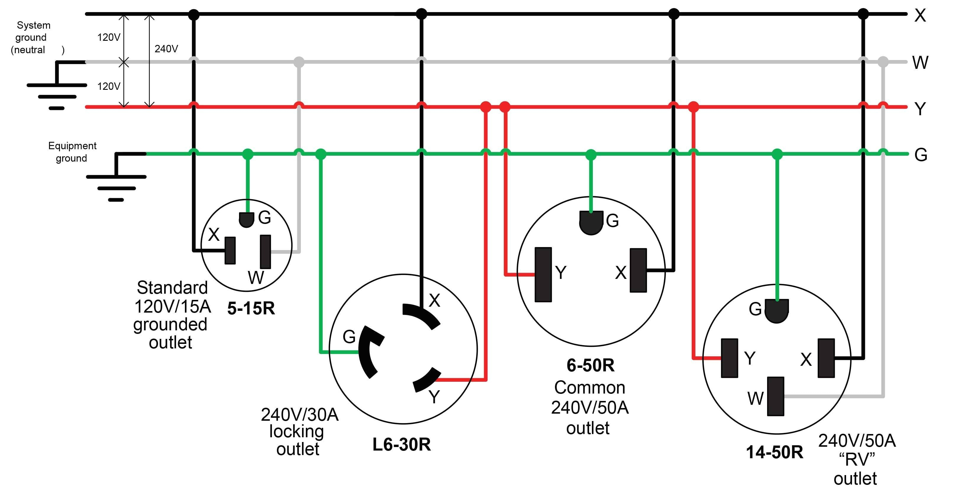
Nema L14 20p Wiring Diagram The nema l14 20p wiring diagram is a visual representation of the connections and wires needed for a nema l14 20p plug. this diagram shows the configuration of the plug’s prongs, which will determine how the plug is wired. the l14 20p plug has four prongs, two hot prongs, one neutral prong, and one ground prong. The “20p” indicates that it is a 3 pole, 4 wire connector. the wiring diagram for the l14 20p connector follows a specific color coding. the “x” prong is generally colored black and is the “hot” wire, carrying the current. the “y” prong is colored red and is also a “hot” wire. the “w” prong is typically colored white and. •make certain there are no loose strands outside the wire chambers. 9. tighten terminal screws securely •torque screws to 14 16 in lb (1.6 1.8 n m). • make certain there is no wire insulation under any terminal clamp. 10. reassemble plug •reinsert plug insert into backshell. note that a keyway in the housing and body properly. Another crucial factor in nema l14 20 wiring is the correct installation and grounding of the outlet. the nema l14 20 wiring standard includes specific guidelines for properly grounding the outlet to protect against electrical shocks. improper grounding can create a risk of electrical shock and damage to connected devices.

How To Wire A 2 Speed Cooler Motor A Complete Wiring Diagram Guide •make certain there are no loose strands outside the wire chambers. 9. tighten terminal screws securely •torque screws to 14 16 in lb (1.6 1.8 n m). • make certain there is no wire insulation under any terminal clamp. 10. reassemble plug •reinsert plug insert into backshell. note that a keyway in the housing and body properly. Another crucial factor in nema l14 20 wiring is the correct installation and grounding of the outlet. the nema l14 20 wiring standard includes specific guidelines for properly grounding the outlet to protect against electrical shocks. improper grounding can create a risk of electrical shock and damage to connected devices. A 2 speed cooler motor wiring diagram typically includes the components of the motor, the power supply, the control switch and the wiring connections. the diagram will also include information about the voltage, current, and any other specifications that are necessary for the motor to operate. it is important to ensure that all of the. Feed the power cord through the hole in the rear part of the housing, separate the wires and strip about ½ inch of insulation from the end of each one. you will find four wires in the cord. they are red, black, white and green or bare. the black and red wires are hot and they go on the two brass terminals in the front of the housing.

Nema L14 20p Wiring Diagram A 2 speed cooler motor wiring diagram typically includes the components of the motor, the power supply, the control switch and the wiring connections. the diagram will also include information about the voltage, current, and any other specifications that are necessary for the motor to operate. it is important to ensure that all of the. Feed the power cord through the hole in the rear part of the housing, separate the wires and strip about ½ inch of insulation from the end of each one. you will find four wires in the cord. they are red, black, white and green or bare. the black and red wires are hot and they go on the two brass terminals in the front of the housing.

Comments are closed.